Compression springs
Compression springs
- Wire thickness: 0.1mm – 6.00mm
- Wire cross sections: Round,Rectangular,Sqaure and Oval
- Materials: carbon wires, stainless wires, oil-tempered wires, non-ferrous spring wires, special alloys
- Application examples: airbag systems, braking systems, locking systems, control and battery, damping systems, hinges and actuators, Medication Devices.
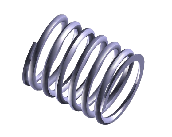
About Compression Springs
These springs are among the most common types of springs used in various industries and applications due to their simplicity and efficiency.
Custom Manufacturing Capabilities
Material
Finish
Wire Sizes & End Types
Compression Spring Information & Resources
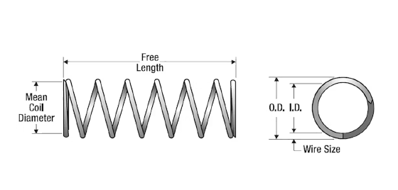
Dimensions Measurement Guide
1. Hold the base of the spring in one hand, and the Calipers in the other hand.
2. Place the Calipers on the outside of the last coil, measuring the largest dimension. This is called the Outside Diameter (O.D.).
3. Place the Calipers on the wire in the center of the spring. This is called the Wire or Material Size. You should also measure the wire
toward one end for comparison and accuracy.
4. Place the Calipers on the full length of the uncompressed spring. This is called Free Length.
5. Count the total coils, beginning at one end, just next to where the wire has been cut. Be sure you count all coils, including any portion of a coil. (seediagram for example)
Design Information
Minimum Tensile Strength (MTS) values vary with the spring-wire diameter. Further, 30 to 45 percent of the MTS value, depending on the material type, is used as a corrected stress target to produce a long fatigue life. For more information on MTS values by material type.
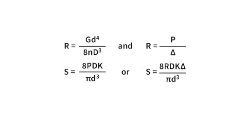
The basic compression rate and wire stress for a compression spring can be estimated with the formulas shown on the right.
Note: One should not employ the curvature (k) correction stress in an expression solving for deflection. Use the uncorrected stress only, or errors will occur. The uncorrected stress can be used for static applications.
Where:
d = Wire diameter, inches
G = Modulus (spring steel = 11.5×10⁶, stainless = 10×106), p.s.i.
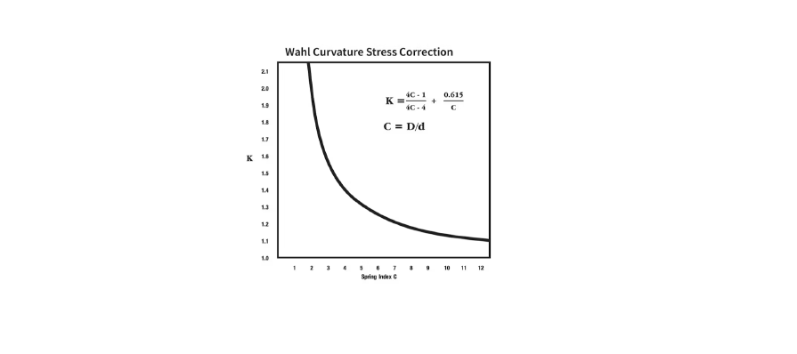
K = Stress correction factor (see plot below)
N = Number of total coils
n = Number of active coils
P = Applied load, pounds
p = Pitch, distance between centerlines of wires of adjoining coils
R = Spring rate, pounds per inch (lbs./in.)
S = Wire stress, psi
Δ = Deflection, inches
π = 3.14
Spring Stress Rate
Type of Spring Ends
| Spring Characteristics | Open | Open & Ground | Closed | Closed & Ground |
|---|---|---|---|---|
| Solid Length | d (N + 1) | d x N | d (N + 1) | d x N |
| Active Coils | N | N – 1 | N – 2 | N – 2 |
| Total Coils (N) | n | n + 1 | n + 2 | n + 2 |
| Free Length (L) | (p x N) + d | p x N | (p x n) + 3d | (p x n) + 2d |
Spring Characteristics
• Service Life
It should be noted that if critical force-versus-deflection linearity is required, only the center 20 to 80 percent of the available deflection range should be
employed. Thus, reserve at least the first and last 15 to 20 percent of the range for potential spring-end and adjacent coil-contact effects. These effects
can be largely ignored for the majority of spring applications. The column “Suggested Maximum Deflection” found in the following pages of inventory
reflects the recommended inches of travel to obtain a statistical service-life of approximately 100,000 cycles (deflections) with infrequent breakage. This
can be realized if the spring in question is not subjected to shock loads, rapid cycling, temperature extremes, corrosion or stress values above those
previously recommended. If the spring is statically loaded (not cycling), a near-infinite life can be expected.
• Ends
The compression spring ends configuration is indicated in the “Ends” column of our inventory listings which are: Closed (C) – The last coil at each end is
bent back to touch the previous coil to create a flat base. Closed and Ground (C&G) – The closed ends of a spring ground to a more accurate flat base.
This will also reduce the solid length. Open (O) – The spring end coils remain open, maintaining the spring machine’s helical wind shape.
• Materials
The highest grades of spring wire are used for fabricating our springs.
• Tolerances
Compression springs characteristically have an hourglass shape when coiled on an automatic coiler; therefore, outside/inside tolerancing is applied to end coils only. This is an important consideration when selecting a spring that fits over a rod or inside a cylinder. Contact us for a custom quote, if tighter tolerance values are required.
Regarding angle tolerance, the plane of the ground end of a spring is usually within five degrees of the perpendicular-to- the-body axis of the spring.
Please note, springs with a coil count less than 4 are made to physical dimensions only. The rate is not certified because of the low amount of active
coils. The listed solid height dimension is for reference only.
• Direction of Helix (Wind)
The wind direction of our stock springs varies, both RHW and LHW. Stock springs are not sorted for wind direction. To order springs wound to a specific
direction, please contact us for a custom quote.
