Torsion
Torsion
- Wire thicknesses: 0.30 mm – 6.00 mm
- Wire cross sections:Round,Rectangular,Sqaure and Ova
- Materials: Carbon steel, Stainless wires, non-ferrous spring wires,special alloys
- Application example: Actuators, Door locking systems, sun protection systems,WM Top Lids
About Torsion Springs
How Torsion Springs Work
Life Expectancy of a Torsion Spring
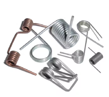
Types of Torsion Springs: Single vs Double Torsion Springs
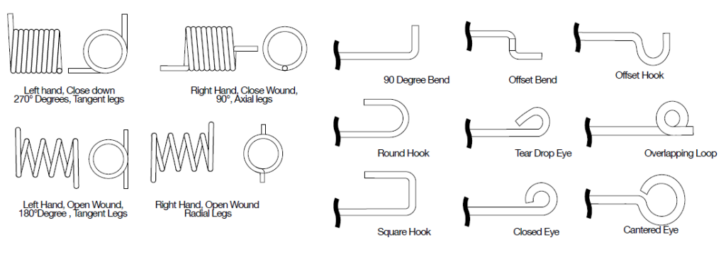
Torsion Spring Configurations
Torsion Spring End Types
Material

Wire Sizes & End Types
Wire Types
Typical Torsion Spring Tolerances
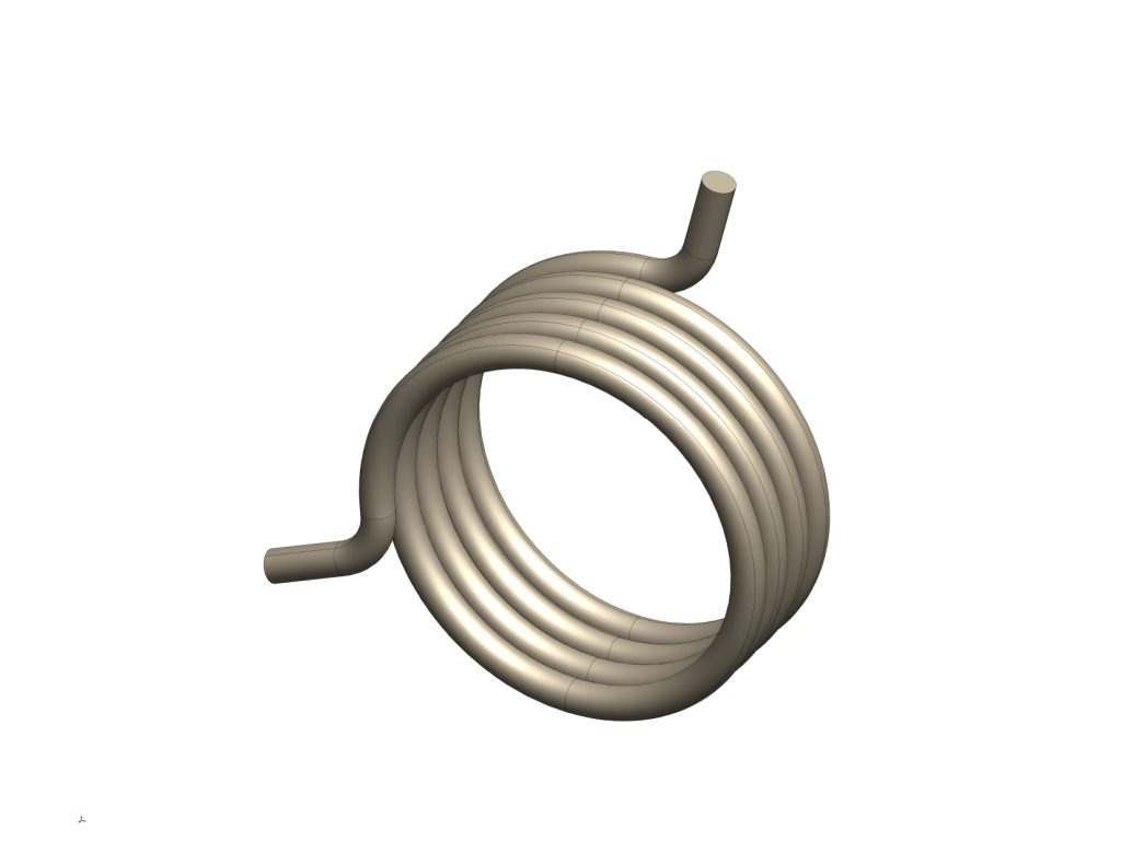
How Are Torsion Springs Designed & Configured?
The torsion spring configuration is designed for the purpose of storing and releasing angular energy or for the purpose of statically holding a mechanism in place
by deflecting the legs about the body center line axis. A spring of this type will reduce in body diameter and increase slightly in body length when deflected in the
preferred direction of the fabricated wind.
When designing a torsion spring, it’s important to consider your application and whether you will need round, rectangular, or shaped wire, such as square wire.
The simplest and most common torsion spring designs are single body torsion springs made from rectangular wire with straight ends, although this design format
can be modified with bends and formed shaped.
The direction of the fabricated wind can also be important for torsion spring applications due to the leg bearing/attachment location having to be on the left or right
side upon assembly. A torsion spring is normally supported by a rod (mandrel) that is coincident with the theoretical hingeline of the final product.
Double torsion spring designs are more complex and will need to consider manufacturing method. Double torsion springs are coiled from the center, as opposed
to single torsion springs, which are coiled from the ends. For details on torsion spring design for both single and double body torsion springs, reach out to our
engineering team through our Ask an Expert form.
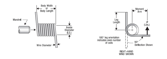
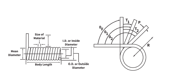
How to Measure a Torsion Spring
Correct dimensions are crucial in identifying the right spring for your application. Use the steps and diagram below to measure accurately measure your
torsion springs.
- Hold the spring in one hand, and the calipers in the other hand.
- Place the calliper “teeth” on the inside diameter. This is called the Inside Diameter (I.D.).
- Place the calipers on the “leg” to measure the wire. This is called Material Size (or Wire Diameter).
- Place the calipers on the working coils of the spring. This is called the Body Length. Place the calipers on the working coils of the spring. This is called
the Body Length. - Count the total coils, beginning at one end, just under where the leg leaves the body. Count to the other end, all full coils, and any fraction thereof.
This is called the Number of Coils and determines leg position. i.e. 90°, 180°, etc. - Determine the direction of the coil (Wind Direction). See diagram for hand/finger illustration. Right Hand Wind or Left Hand Wind.
